
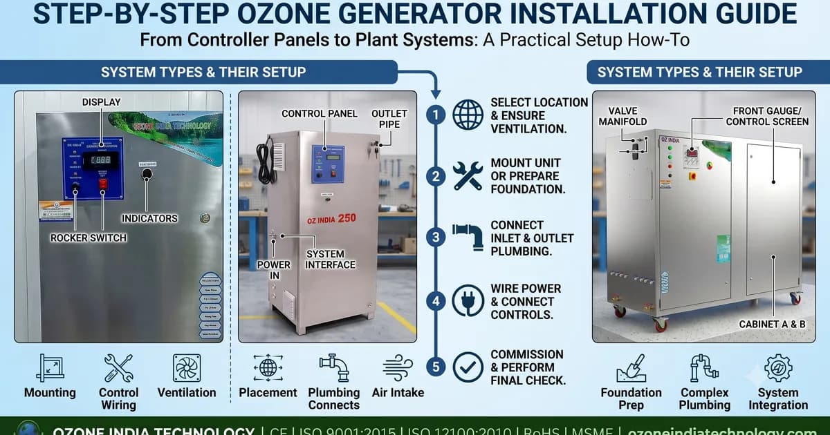
Installing an industrial ozone generator correctly determines whether the system delivers rated ozone output at design water quality — or underperforms from day one due to avoidable errors in site layout, feed gas preparation, ozone injection, contact chamber design, or safety interlock wiring. The majority of ozone generator field problems — reduced output, generator overtemperature shutdown, no dissolved ozone despite generator running — are installation errors, not equipment failures. This step-by-step ozone generator installation guide covers site preparation, feed gas system, ozone injection method selection, contact chamber sizing, off-gas management, safety equipment, control wiring, and commissioning verification, applicable to all industrial ozone generators from 5g/hr to 350g/hr.
Step 1 — Site Selection and Room Requirements
The ozone generator must be installed indoors in a plant room or equipment enclosure. Outdoor installation is not permitted due to moisture ingress and UV degradation of electronics.
Ventilation: The generator room must have a minimum of 10 air changes per hour (ACH) with fresh air inlet and exhaust fan. If ozone gas leaks from any connection, ventilation dilutes it below the 0.1 ppm OSHA/CE exposure limit. Calculate ACH: Fan capacity (m³/hr) ÷ Room volume (m³) ≥ 10.
Temperature: Generator ambient temperature must be 5–40°C. Above 40°C, the corona cell derates automatically. Below 5°C, the desiccant dryer efficiency reduces and the control electronics may not start reliably. In hot climates (generator rooms above 40°C), install a dedicated split AC unit in the generator room.
Clearance: Minimum 0.5 m clearance on all sides and above the generator for cooling airflow. Do not install the generator directly against a wall or in an enclosed cabinet without adequate ventilation.
Power: Provide a dedicated earthed power circuit (not shared with other equipment). Single-phase 230V/16A for units up to 25g/hr; three-phase 415V for 30g/hr+ units. Install an appropriately rated MCB and isolation switch within 1 m of the generator for lockout/tagout during maintenance.
Common Installation Errors and Their Impact on Ozone Output (% output loss)
Step 2 — Feed Gas Preparation
Feed gas quality is the most critical installation factor. All moisture must be removed before gas enters the corona cell.
Air-fed systems (2–50g/hr units):
- Install an oil-free air compressor (compressor capacity: minimum 2× the generator's air consumption in L/min, typically stated in the technical datasheet)
- Install a refrigerant air dryer to dewpoint -20°C as the first stage
- Install the desiccant dryer (silica gel, supplied with the generator) as the second stage, achieving dewpoint -50°C to -70°C
- Install a 0.01 micron coalescing filter between the compressor and dryer to remove oil aerosols — oil contamination in the corona cell causes carbon deposits and irreversible dielectric damage
- Set compressor output pressure to match the generator's rated inlet pressure (typically 0.5–1.5 bar — check datasheet)
Oxygen-fed systems (50g/hr+ for demanding applications):
- Install a PSA oxygen generator sized at 1.2–1.5× the ozone generator's oxygen consumption (rule: O₂ consumption (Nm³/hr) = Ozone output (g/hr) ÷ 1000 × 0.0015 × 1.3 × 1000 / 0.93)
- Connect PSA outlet (93% O₂, dewpoint ≤-40°C) directly to the ozone generator oxygen inlet
- No additional dryer is required for PSA oxygen — PSA process inherently produces dry oxygen
Feed gas lines: Use only ozone-compatible tubing — PVDF (polyvinylidene fluoride) or 316L stainless steel tube. Standard PVC tube must not be used for ozone generator gas lines — it degrades rapidly under ozone and off-gasses compounds that contaminate the corona cell.
Step 3 — Ozone Injection into Process Water
Three methods for introducing ozone into water; choose based on flow rate and available pressure:
Venturi injector (recommended for 0.1–100 m³/hr): The ozone venturi injector is installed on a sidestream pipe (5–20% of total flow). Process water enters at 1–4 bar, ozone gas is drawn in by venturi vacuum. The PVDF venturi is installed with inlet and outlet isolation valves for maintenance. Run a short (1–3 m) PVDF tube from the generator outlet to the venturi gas inlet — no check valve is needed on gas-side if the venturi operates at positive water pressure. Install an ozone NRV between the generator outlet and venturi to prevent water backflow if the water pump stops.
Fine bubble diffuser (for large tanks and swimming pools): Submerge the ozone air diffuser at the bottom of the contact chamber. Connect the diffuser to the generator with a PVDF tube (no metal-to-metal joints) with an ozone NRV. Fine bubble diffusers achieve 80–90% transfer efficiency in tanks with ≥3 m water depth and 5–15 minutes contact time.
Static mixer (supplement to venturi): Install an ozone static mixer inline downstream of the venturi injector to enhance dissolution. The static mixer reduces dissolved ozone contact chamber requirements by 30–40% by improving transfer efficiency to 95%+.
Ozone Transfer Efficiency by Injection Method (%)
Step 4 — Contact Chamber Design and Installation
The contact chamber provides residence time for ozone to react with pathogens and oxidise organic compounds. It is not optional — without adequate contact time, the CT value (Concentration × Time) required for pathogen inactivation is not achieved.
Sizing formula: Volume (m³) = Flow rate (m³/hr) × Contact time (min) ÷ 60
- Drinking water: 10–15 minutes → for 10 m³/hr: 1.7–2.5 m³ chamber
- STP disinfection: 5–10 minutes → for 10 m³/hr: 0.8–1.7 m³
- Swimming pool sidestream: 30–60 seconds → for 2 m³/hr: 17–33 litres
- Cooling tower sidestream: 30–60 seconds → for 5 m³/hr: 42–83 litres
Construction: Contact chambers must be constructed of 316L stainless steel. Carbon steel, mild steel, and FRP are not compatible with dissolved ozone at >0.5 mg/L. Install internal baffles to prevent short-circuiting (plug flow is required for accurate CT calculation).
Connections: All inlet, outlet, and drain connections on the contact chamber use PVDF compression fittings or 316L SS flanges. Gaskets: PVDF or PTFE only — rubber gaskets degrade in ozone contact.
Step 5 — Off-Gas Management (Ozone Destructor)
Every contact chamber and contact vessel has an off-gas vent — undissolved ozone that accumulates in the headspace must be safely destroyed before release to the plant room atmosphere.
Install the ozone destructor on the contact chamber off-gas vent:
- Size the destructor for the maximum off-gas flow rate (typically 5–10% of ozone generator gas output by volume, at the contact vessel headspace pressure)
- Connect the contact vessel vent to the destructor inlet with a PVDF tube — destructor inlet accepts 1/4" to 1/2" PVDF tube depending on model
- The destructor outlet vents to atmosphere (outdoors via a small-bore tube, or to the plant room if the destructor is certified for indoor discharge)
- The MnO₂ catalyst cartridge requires no power — it passively converts ozone to oxygen at room temperature
- Install an ozone ambient air monitor downstream of the destructor outlet vent to verify catalyst performance quarterly
Step 6 — Safety Equipment and Interlock Wiring
The following safety systems are mandatory for all industrial ozone generator installations:
Ambient air monitor: Install the ozone ambient air monitor in the generator room at breathing zone height (1.0–1.5 m above floor). Wire the monitor's relay output to the generator's emergency stop (E-stop) input. The standard interlock: ambient ozone >0.1 ppm → relay opens → generator shuts down + alarm horn activates.
Interlock wiring (terminal connections on Ozone India Technology generators):
- Terminal block "SAFE_IN": Connect ambient monitor relay (NC contact, opens on alarm)
- Terminal block "ALARM_OUT": Connect to alarm horn or PLC digital input
- Terminal block "4-20mA_IN": Connect dissolved ozone monitor 4–20 mA output for automatic output control
Process water flow interlock: Wire a flow switch on the process water inlet to the generator E-stop input. If water flow stops, the generator must shut down — running ozone into a static water volume rapidly reaches toxic concentrations and may pressurize contact vessels.
Safety Interlock Priority and Response Time Requirements
Step 7 — Commissioning Checklist
Complete this sequence after all equipment is installed:
Pre-commissioning (power off):
- All gas-side connections leak-tested with soapy water (no bubbles under pressure)
- All water-side connections pressure-tested at 1.5× operating pressure
- Ambient air monitor sensor check (reads 0.03–0.05 ppm in fresh outdoor air)
- E-stop interlock circuit continuity tested (disconnect ambient monitor → generator should not start)
- Feed air dewpoint measured at generator inlet: should be ≤-50°C
- Process water pump running, flow switch indicating "flow present"
Commissioning (power on, step-by-step):
- Start ozone generator at 20% output. Smell-check all gas connections — no ozone odour should be detectable at connections (indicates leak). Ambient monitor should read <0.05 ppm in plant room.
- Increase to 50% output. Measure dissolved ozone at contact chamber outlet with a portable test kit — target should be 0.5–1.0× the design dissolved ozone setpoint.
- Increase to 100% output. Measure dissolved ozone at full output — should reach design target. If not: check venturi for scale (clean with citric acid), check contact chamber for short-circuiting.
- Verify ambient monitor auto-shutoff: place a small piece of ozone-generating material near the sensor (or use calibration gas) to trigger Level 2 alarm — confirm generator shuts down within 30 seconds.
- Document baseline readings: ozone generator output %, dissolved ozone residual, ambient ozone monitor reading, feed gas pressure and dewpoint. These are the reference values for future maintenance.
Conclusion
A correctly installed ozone generator delivers rated dissolved ozone output consistently for years without major intervention. The three most common installation errors — inadequate feed air drying, wrong venturi sizing, and missing ambient monitor interlock — each cause predictable failures that a methodical installation checklist prevents entirely. Ozone India Technology provides commissioning support (remote via video call) for all installed generators. For on-site installation supervision of industrial and municipal projects, contact [email protected] or WhatsApp +91 96500 17943. All accessories — venturi injector, static mixer, ozone destructor, ambient air monitor, and dissolved ozone monitor — are available from Ozone India Technology as a complete system.
