
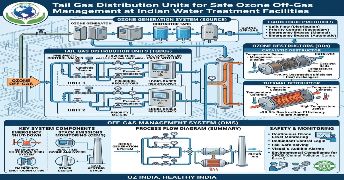
Ozone is the most powerful disinfectant and oxidant commercially available to Indian water treatment engineers — but every ozone water treatment system generates a hazardous by-product that is too often ignored during system design: tail gas. Tail gas, also called ozone off-gas or residual vent gas, is the ozone-laden exhaust discharged from ozone contact tanks, generator purge vents, and system dissolution units. At concentrations of 1,000 to 50,000 mg/m³ — thousands of times above the 0.1 ppm occupational exposure limit — unmanaged tail gas creates an immediate inhalation hazard for plant operators and risks non-compliance with India's National Ambient Air Quality Standards.
Indian water treatment facilities face a unique challenge: CPHEEO guidelines mandate ozone disinfection for Class A drinking water sources, CPCB standards require ozone treatment in STPs and ETPs serving pharmaceutical, food, and textile industries, and the scale of Indian urban water infrastructure — from 0.1 MLD rural supply schemes to 200 MLD metro WTPs — creates enormous variation in tail gas volume and concentration. Yet the tail gas management train — the collection manifold, destructor unit, vent piping, and ambient monitoring system — receives a fraction of the engineering attention given to the ozone generator and contact system.
This guide provides Indian water treatment engineers, environmental managers, and procurement teams with a complete technical specification for tail gas distribution units, catalyst-based ozone destructors, and the ancillary equipment required for safe ozone off-gas management under Indian regulatory requirements.
What Is Tail Gas in an Ozone Water Treatment System
When ozone is dissolved into water in a contact tank, transfer efficiency is typically 80 to 92 percent using fine bubble diffusers or venturi injectors. The remaining 8 to 20 percent of the ozone dose — plus all carrier gas (air or oxygen) — exits the contact tank as tail gas through the headspace vent. This tail gas contains ozone concentrations of 500 to 15,000 mg/m³ depending on:
- Transfer efficiency of the ozone dissolution system (higher transfer = lower tail gas concentration)
- Ozone generator output concentration (higher output % = more concentrated tail gas)
- Headspace volume of the contact tank (larger headspace = more dilution)
- Water temperature (warmer water = lower ozone solubility = more tail gas)
- Contact tank operating pressure (pressurised systems have lower tail gas volume)
Additional tail gas sources in a typical Indian WTP include the ozone generator purge outlet (activated during generator startup and shutdown cycles), ozone system pipeline vents, and the off-gas from ozone monitoring equipment sample returns. Every one of these sources must be collected and routed to a tail gas treatment unit before discharge.
Indian Regulatory Framework for Ozone in Air
Indian water treatment operators must comply with ozone-in-air limits under two distinct regulatory frameworks — ambient outdoor air quality standards that protect the general public, and occupational exposure limits that protect plant workers. Both frameworks must be met simultaneously.
| Regulatory Body | Standard / Notification | Limit | Averaging Period | Coverage |
|---|---|---|---|---|
| CPCB / MoEF | NAAQS 2009 — S.O. 3305(E) | 100 µg/m³ (0.05 ppm) | 8-hour average | Outdoor ambient — general public |
| CPCB / MoEF | NAAQS 2009 — S.O. 3305(E) | 180 µg/m³ (0.09 ppm) | 1-hour average | Outdoor ambient — general public |
| BIS / IS 7993 | Safety Code — Ozone Handling | 0.1 ppm (196 µg/m³) | 8-hour TWA | Occupational — WTP operators |
| Ministry of Labour | Factories Act Schedule III | 0.1 ppm | 8-hour TWA | Factory / industrial workers |
| NIOSH (reference) | Recommended Exposure Limit | 0.1 ppm | 10-hour TWA | Occupational guidance |
| WHO AQG 2005 | Air Quality Guideline | 100 µg/m³ (0.05 ppm) | 8-hour average | Health-based global reference |
| OSHA (reference) | 29 CFR 1910.1000 Table Z-1 | 0.1 ppm | 8-hour TWA | Occupational reference for CE equipment |
The critical compliance boundary for Indian WTP operators is the CPCB NAAQS 8-hour limit of 100 µg/m³ at the plant boundary and the BIS IS 7993 occupational limit of 0.1 ppm (196 µg/m³) in the ozone equipment room. Unmanaged tail gas from even a 10 g/hr ozone generator will exceed both limits within seconds in an enclosed equipment room.
Ozone Exposure Limits by Indian and International Standard (µg/m³, 8-hour)
Components of a Complete Tail Gas Management System
A properly engineered tail gas distribution system at an Indian water treatment facility consists of six functional components. Each component must be specified for ozone service — conventional materials including PVC, rubber gaskets, copper fittings, and standard carbon steel will be attacked by ozone concentrations found in tail gas.
| Component | Function | Material Specification | Required For |
|---|---|---|---|
| Off-gas collection manifold | Collects tail gas from all contact tank headspaces and generator vents into a common header | SS 316L or PVDF piping; PTFE gaskets; minimum DN25 | All ozone contact tanks, generator purge outlets |
| Condensate separator | Removes moisture from humid Indian air before it enters destructor catalyst bed | SS 316L body; PTFE seal; drain to ozone-treated drain point | Essential — Indian monsoon humidity causes catalyst bed flooding without this |
| Catalytic ozone destructor | Decomposes O₃ to O₂ via MnO₂ or activated alumina catalyst at ambient temperature | SS 316L or PVDF vessel; MnO₂ catalyst bed; PTFE seals | All ozone installations — mandatory for regulatory compliance |
| Ozone ambient air monitor | Continuous electrochemical sensing in the ozone equipment room; audible and relay alarm at 0.1 ppm | Range 0–1 ppm or 0–5 ppm; IP54 or better; 4–20 mA output; relay for alarm | All enclosed ozone equipment rooms |
| Treated exhaust vent | Conveys destructor outlet gas (safe O₂-enriched air) to outdoor atmosphere above roof level | SS 316L or UPVC (safe at destructor outlet — ozone destroyed); minimum 3 m above roof | All indoor installations |
| Catalyst replacement monitoring | Outlet ozone sensor or service interval indicator to ensure timely MnO₂ catalyst replacement | Outlet electrochemical sensor at 0–1 ppm range, or timed maintenance schedule (24 months) | All destructors — catalyst exhaustion is the single most common tail gas management failure |
The Catalytic Ozone Destructor — Engineering Principle
The catalytic ozone destructor is the primary active component in any tail gas management system. Indian WTP operators frequently ask whether a simple long vent pipe to atmosphere is sufficient — the answer is emphatically no. Even diluted to 10 ppm at the vent discharge point, ozone above CPCB NAAQS limits will accumulate downwind under stable atmospheric conditions common in Indo-Gangetic Plain WTPs during winter mornings.
A catalytic destructor using manganese dioxide (MnO₂) catalyst operates by the following decomposition pathway at ambient temperature:
2O₃ → 3O₂ (catalysed by MnO₂ surface)
This reaction is exothermic (+143 kJ/mol) but generates only mild temperature rise (5–15°C above ambient) at the flow rates encountered in WTP tail gas service. No external heat source, electrical power, or water supply is required for catalyst-based destructors — a significant operational advantage for Indian WTPs where power reliability is a concern. The complete conversion of ozone to oxygen means the exhaust from a properly functioning destructor is simply oxygen-enriched clean air.
MnO₂ catalyst beds achieve 99.9% ozone destruction efficiency when:
- Inlet gas is dry (relative humidity < 80%) — hence the condensate separator requirement in Indian monsoon conditions
- Gas flow rate is within the rated GHSV (gas hourly space velocity) of the catalyst bed
- Catalyst is within service life (typically 18–30 months at Indian WTP tail gas conditions)
- Inlet ozone concentration is below 15% by weight (all WTP tail gas is well within this limit)
Catalytic Destructor Outlet Ozone vs Catalyst Age — MnO₂ Bed at Rated Flow (mg/m³)
The chart above underscores why catalyst replacement scheduling is the most critical maintenance activity in tail gas management. An exhausted catalyst bed provides essentially zero protection — the outlet concentration approaches the inlet concentration. Indian WTP operators should schedule catalyst replacement at 24-month intervals regardless of visual condition, and install an outlet ozone sensor to detect premature exhaustion caused by overload events.
Tail Gas Off-Gas Concentrations at Key WTP Process Points
Understanding the ozone concentration in tail gas at each process point in the WTP is essential for correct destructor sizing and pipeline material selection. Concentrations vary by three orders of magnitude between the generator purge outlet and the ambient equipment room air.
Typical Ozone Off-Gas Concentration at WTP Process Points — Before Destructor (mg/m³)
The generator purge stream carries the highest concentration because it comes directly from the corona discharge cell without any dissolution step. This stream must be routed directly to the destructor inlet — it must never be vented to the equipment room, even momentarily during system startup. A hardwired interlock that opens the destructor bypass valve before the generator purge valve is a recommended safety design for all Indian WTP ozone installations above 25 g/hr.
Sizing Tail Gas Destructors for Indian WTP Capacities
Destructor sizing is governed by the volumetric gas flow rate at the destructor inlet, not by the ozone concentration. The total tail gas flow rate includes: carrier gas flow from the ozone generator (typically 10–25 NL of air per gram of ozone generated at 5–8% concentration), plus headspace breathing volume from contact tanks as water levels fluctuate.
| WTP Capacity | Ozone Dose Required | Generator Size | Total Tail Gas Flow | Destructor Capacity Required | Contact Tank Configuration |
|---|---|---|---|---|---|
| 0.1 MLD | 200–500 g O₃/day | 10–25 g/hr | 20–60 NL/min | 100 NL/min (with 50% safety factor) | 1 contact tank |
| 0.5 MLD | 1–2.5 kg O₃/day | 25–75 g/hr | 60–180 NL/min | 300 NL/min | 1–2 contact tanks |
| 1 MLD | 2–5 kg O₃/day | 50–150 g/hr | 120–350 NL/min | 600 NL/min | 2 contact tanks |
| 5 MLD | 10–25 kg O₃/day | 250–750 g/hr | 600–1800 NL/min | 3,000 NL/min | 2–3 contact stages |
| 10 MLD | 20–50 kg O₃/day | 500 g/hr–1.5 kg/hr | 1,200–3,600 NL/min | 6,000 NL/min | 3 contact stages |
| 50 MLD | 100–250 kg O₃/day | 2.5–7.5 kg/hr | 6,000–18,000 NL/min | 30,000 NL/min | Multi-stage, parallel trains |
Important: The 50% safety factor above the maximum calculated flow rate is mandatory for Indian conditions. Indian WTPs frequently experience flow surges, emergency ozone overdose conditions during microbial event responses, and carrier gas supply interruptions that increase purge gas volumes. Undersizing the destructor causes it to operate outside its rated GHSV, reducing efficiency precisely when safety is most critical.
Required Destructor Tail Gas Handling Capacity by Indian WTP Plant Size (NL/min)
Ozone Event Management — What Happens When the System Fails
An "ozone event" in Indian WTP terminology refers to any condition where ozone reaches the equipment room or surrounding areas at concentrations above the 0.1 ppm exposure limit. Ozone events have four common causes in Indian WTPs:
1. Catalyst exhaustion — The most common failure mode. MnO₂ catalyst loses activity gradually; many Indian WTPs operate destructors for 3–5 years without catalyst replacement, resulting in near-zero destruction efficiency.
2. Manifold disconnection — Tail gas collection pipework is disconnected for maintenance and not reconnected before the ozone system is restarted. This is the most dangerous event type and the leading cause of acute ozone exposure incidents in Indian industrial ozone installations.
3. Contact tank seal failure — Gasket failure at tank flanges or cover plate joints allows tail gas to bypass the collection manifold and discharge directly to the equipment room.
4. Generator purge mismanagement — Generator purge gas is vented during startup or shutdown through a manual bypass rather than through the destructor, creating a brief but high-concentration release.
All four event types are preventable through proper tail gas distribution system design, an ozone ambient air monitor with interlock capability, and a documented operating procedure for ozone system startup and shutdown.
Ozone India Technology Products for Tail Gas Management
Ozone Destructor — Catalytic CE Certified
Ozone India Technology's catalytic ozone destructor uses a manganese dioxide catalyst bed to achieve 99.9% ozone destruction efficiency at ambient temperature — no power consumption, no moving parts, no water supply required. Available for tail gas flows from laboratory-scale (5 NL/min) to large WTP applications (10,000+ NL/min). CE certified, ISO 9001:2015. Catalyst replacement available from our Ghaziabad facility with 48-hour pan-India courier delivery.
Applications: STP ozone system off-gas, ETP ozone contact tank exhaust, drinking water WTP tail gas, ozone test chamber exhaust, pharmaceutical ozone system vents.
Key specification: MnO₂ catalyst, 99.9% efficiency at rated GHSV, ambient temperature operation, SS 316L or PVDF body (ozone-rated), PTFE gaskets, inlet and outlet flanges per DIN standard, catalyst replacement without system shutdown.
Ozone Ambient Air Monitor — Real-Time Equipment Room Protection
An ozone ambient air monitor is mandatory in any enclosed space containing ozone equipment, tail gas pipework, or contact tanks. Ozone India Technology's ambient air monitor uses an electrochemical sensor with a measurement range of 0–1 ppm, audible alarm, and relay output for integration with the ozone system control panel. When the ambient monitor detects ozone above 0.1 ppm, the relay output can be configured to activate an exhaust fan, trigger the ozone generator emergency shutdown, or alert the control room.
Placement guidance for Indian WTPs: Install at operator breathing zone height (1.2–1.5 m above floor), within 3 m of the ozone contact tank exhaust connection point, and at the ozone generator control panel. For large WTP buildings with multiple ozone trains, one monitor per 200 m² of equipment room floor area is recommended.
→ View Ozone Ambient Air Monitor
Ozone Dissolve Monitor — Contact Tank Process Control
The ozone dissolve monitor measures dissolved ozone concentration in the contact tank effluent, providing the process control signal needed to maintain the correct ozone dose while minimising tail gas generation. Overdosing — the most common cause of high tail gas concentrations in Indian WTPs — can be eliminated by automatic ozone generator output control via a dissolved ozone signal. A dissolved ozone monitor is therefore both a process optimisation tool and a tail gas management tool.
Ozone Generator Range — For Indian WTP Scales
The ozone generator is the upstream component that determines the tail gas management system specification. Ozone India Technology manufactures corona discharge ozone generators from 2 g/hr to 10 kg/hr to cover every Indian WTP capacity from a small rural scheme to a major urban water treatment plant. Our generators include an integrated air dryer (refrigerant or desiccant) — critical because dry feed air produces concentrated ozone that dissolves more efficiently into water, reducing the volume and concentration of tail gas generated.
- Ozone Generator 10–25 g/hr — for WTPs up to 0.5 MLD
- Ozone Generator 30–50 g/hr — for WTPs 0.5 to 1 MLD
- Ozone Generator 75–350 g/hr — for WTPs 1 to 10 MLD
- Ozone Generator 400 g/hr–1 kg/hr — for large municipal WTPs
Indian Climate Considerations for Tail Gas System Design
Indian water treatment facilities operate under climate conditions that demand specific adaptations to standard tail gas management designs used in European or North American WTPs.
High humidity (monsoon, coastal regions): Ambient relative humidity above 85% in monsoon season causes moisture condensation in tail gas pipework and saturation of the MnO₂ catalyst bed. A condensate separator upstream of the destructor — with an automatic drain to the plant drain system — is mandatory for all Indian installations. Catalyst bed flooding reduces ozone destruction efficiency and shortens catalyst life from 24 months to as little as 6 months.
High ambient temperature (Indo-Gangetic Plain summer): Equipment room temperatures above 45°C in May–June in UP, Rajasthan, and Delhi NCR can affect both the ozone ambient air monitor sensor and the catalytic destructor performance. Both units should be specified for operation to 55°C ambient. Electrochemical ozone sensor cells used in ambient monitors have reduced accuracy and shorter service life above 40°C — annual sensor replacement is advisable for equipment rooms without air conditioning.
Power supply reliability: Many Indian WTPs, particularly those operated by urban local bodies (ULBs) in Tier 2 and Tier 3 cities, experience regular power interruptions. An ozone generator that restarts automatically after power restoration without operator intervention will produce a high-concentration purge gas burst — this must flow through the destructor, not bypass it. The control system interlock sequencing (destructor flow confirmed → generator allowed to start) should be verified as part of the commissioning protocol.
Compliance Documentation for Indian WTP Ozone Events
Indian water utilities submitting ozone treatment systems for CPHEEO approval, CPCB consent renewal, or MOEF environmental clearance must demonstrate that their tail gas management system meets NAAQS 2009 ambient air quality standards at the plant boundary. Documentation required includes:
- Ozone ambient air quality monitoring data from the plant boundary receptor point
- Catalytic destructor efficiency verification (inlet and outlet ozone concentration measurements at commissioned flow rate)
- Ozone equipment room ambient air monitoring records (electrochemical sensor log)
- Catalyst replacement records and catalyst condition verification protocol
- Emergency ozone event response procedure (OERP) — documented shutdown sequence and evacuation protocol
- HAZOP study extract covering ozone tail gas scenarios (required for plants >10 g/hr in industrial zones under CPCB consent conditions)
Ozone India Technology provides a complete compliance documentation package with every ozone system supply — including the destructor efficiency commissioning report, ambient monitoring protocol, and a template OERP for the specific installation. This documentation package is provided at no additional charge as part of our standard supply.
Why Ozone India Technology for Tail Gas Management at Indian WTPs
Ozone India Technology is India's leading CE and ISO 9001:2015 certified manufacturer of ozone generators, catalytic ozone destructors, and ozone monitoring systems. Our 11 years of experience includes tail gas management system design for pharmaceutical ozone systems under CDSCO Schedule M, food processing ozone rooms under FSSAI, STP ozone systems under CPCB consent conditions, and drinking water WTPs under CPHEEO guidelines.
Our IIT Patna-educated engineering team provides free ozone system design review — including tail gas flow calculation, destructor sizing, manifold layout, and ambient monitoring placement — for every new installation. We supply complete ozone packages: generator, destructor, ambient monitor, dissolved monitor, venturi injector, and all interconnecting ozone-rated pipework, sized and specified as an integrated system.
Factory-direct pricing from our Greater Noida manufacturing facility is 30 to 40 percent below imported European alternatives, with the same CE certification and equivalent technical performance. We stock catalytic destructor catalyst for same-day dispatch across India.
Call +91 96500 17943 or WhatsApp 919650017943 for a free tail gas management system sizing consultation. Our team responds to technical enquiries within 2 hours on working days.